Calculating the Required Voltage
For effective testing, the output voltage must lie between certain upper and lower limits. The upper voltage limit is that at which the coating itself would breakdown and be damaged. Therefore, the test voltage should be lower than this value. The lower limit is the voltage required to break down the thickness of air equivalent to the specified coating thickness. If the output voltage is not greater than this value then a flaw will not be detected.
Whatever the material, if a high enough voltage is applied, it will conduct electricity. However, for insulators (paint, for example) the level of voltage required to achieve a current flow usually results in irreversible material damage.
The voltage that a particular thickness of material is able to resist is termed the dielectric strength. This is usually expressed as the voltage per unit distance, e.g. kV/mm. Its value depends on other parameters such as temperature and humidity.
The upper voltage limit is the dielectric strength of the material multiplied by the specified coating thickness. The lower voltage limit is the dielectric strength of air multiplied by the thickness on the specification.
The dielectric strength of coating materials usually lies in the region of 6kV/mm to 30kV/mm. The dielectric strength of air ranges from 1.3kV/mm to 4kV/mm.
The Lower Limit
The lower limit for effective operation is that required to breakdown the thickness of air equivalent to the specified coating thickness. The breakdown voltage of a given thickness of air varies with humidity, pressure and temperature but is approximately 4kV/mm (0.1 kV/ml).
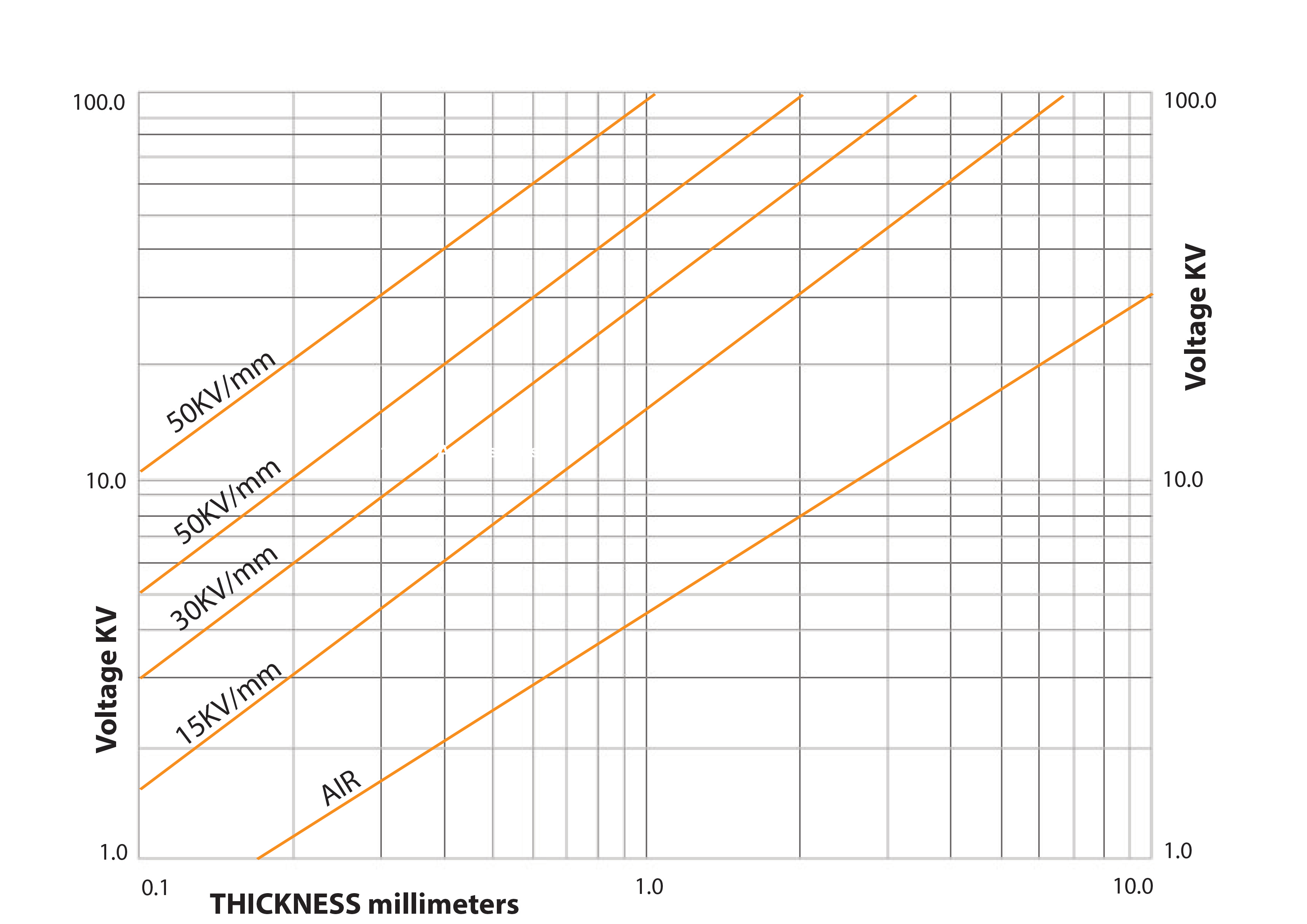
If the specified coating thickness is known, the lower limit value can be read from this graph, using the line marked AIR. For instance, if the specified coating thickness is 1.0mm then the lower limit is 4.5kV.
If the expected coating thickness is not known then the minimum value has to be established experimentally. Turn the output voltage to zero and position the probe over an unprotected area of substrate at the normal height of the coating surface. Turn the voltage up slowly and steadily until a spark is produced and note the voltage. This voltage forms the lower limit.

The Upper Limit
The upper voltage limit may be determined by:
- The job specification: if available and a test voltage is stated
- The dielectric strength: if specified for the applied coating
Measure the thickness of the layer and refer to the previous chart. Alternatively, calculate the maximum voltage, allowing for variations in the coating thickness. Note that 1kV per mm is equivalent to 25.4V per mil (thou).
Please note, this method is only suitable if the dielectric strength values were determined for a DC voltage.
Experiment: Touch the probe on an unimportant area of the work piece. Increase the voltage slowly and steadily until a current passes through the coating and note the voltage. The dielectric strength can be calculated by dividing this voltage by the coating thickness.
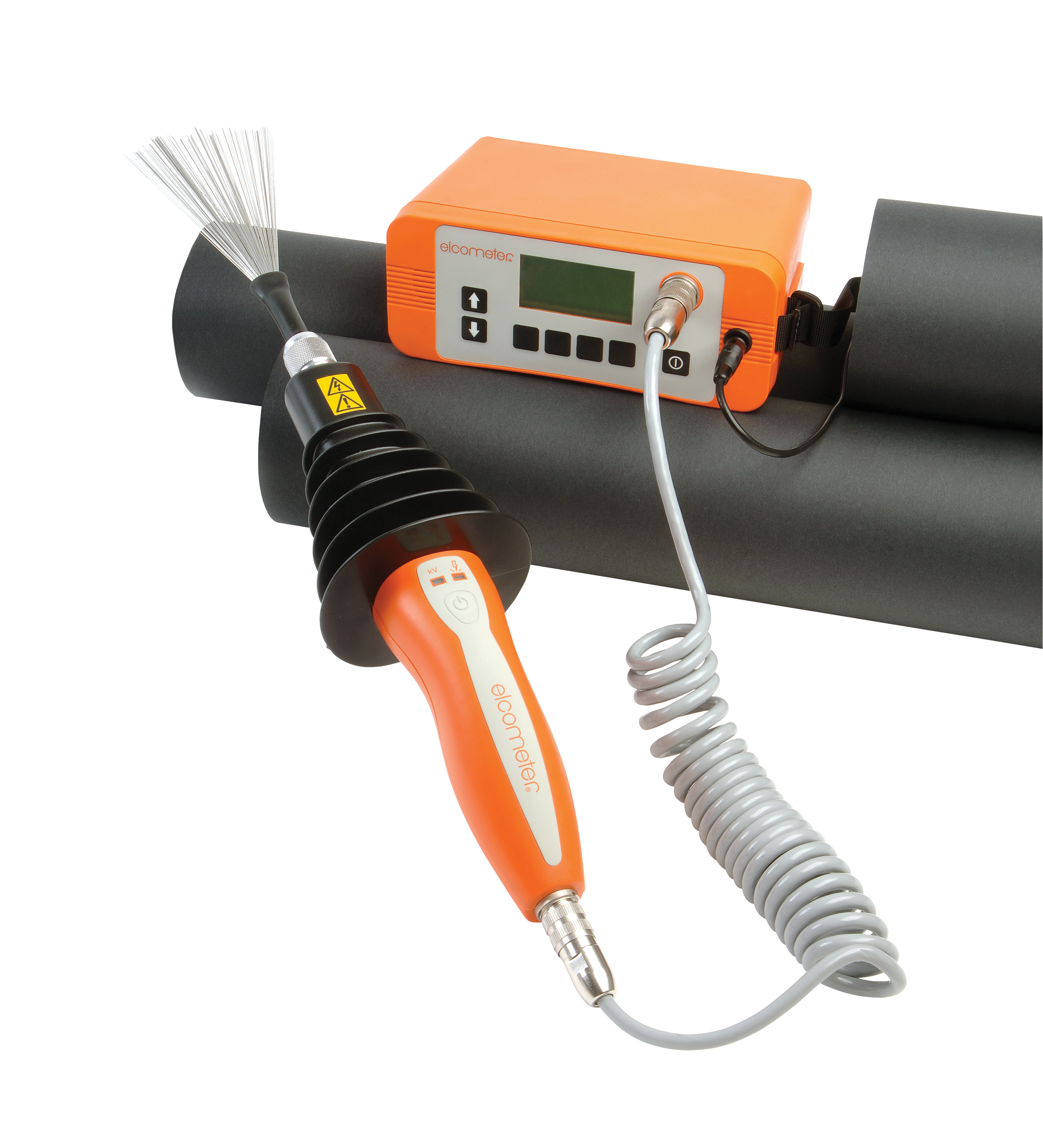
Working on the same principle as the Elcometer 236 DC Holiday Detector, there are more sophisticated gauges on the market which offer the ability to calculate the required voltage, amongst other enhanced features. One such gauge is the Elcometer 266 DC Holiday Detector. This is also a continuous DC high voltage holiday detector. The Elcometer 266 includes a built-in voltage calculator which will determine and set the correct test voltage based upon the test standard and the specified thickness of coating being tested.
Using the Voltage Calculator is a two stage process;
- first select your test standard,
- and then select your coating thickness as per the job specification.

