
Inspection After Surface Preparation
The surface appearance of the steel after blast cleaning is referred to in the Pictorial Standards. The ISO 8501-1 standard (Swedish Rust Standard) identifies the appearance using grades of cleanliness together with reference pictures.
As with the rust grades discussed earlier, there are four grades of cleanliness for abrasive blast cleaning of new steel, these are as follows for A Grade steel:
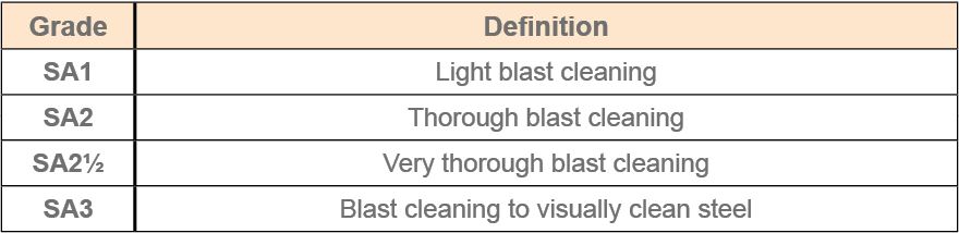
The specification for the coating will detail which grade of cleanliness is required. To assess the cleaned surface, it should be compared to the appropriate photographs in the Standard. Beware, these Standards are often referred to as 'Profile Standards' but this is not the case. Instead, they are Surface Cleanliness Standards - the two are commonly confused.
Note: For different grades of steel (B, C and D steels), there are different cleanliness grades (SB, SC and SD). These are also referred to in the ISO 8501-1 Standard with the relevant photographs. There are also different cleanliness grades for flame-cleaned and water-cleaned substrates.
Flame cleaning is the process of cleaning a structural steel surface by passing a very hot oxyacetylene flame over it. An oxygen-fuelled torch is used parallel with the surface to melt and blow off any blemishes that the operator wants to, including some of the hardest to clean substances such as lubricants and grease. There are also visual cleanliness Standards available for other substrate types such as concrete.
Please note there are several versions of Pictorial Standards and the choice of which standardise used is stated in the job specification. Below is a list of those most frequently used:
- ISO 8501-1 (Swedish Rust Standard)
- SSPC VIS 1-01 (SSPC equivalent to Swedish Rust Standard)
- SSPC VIS-2 (Degree of rusting on painted surfaces)
- SSPC VIS-3 (Hand and Power Tools)
- SSPC VIS-4 (Water jetting)
- SSPC VIS-5 (Wet abrasive)
- BS EN ISO 8501-4 (High pressure water jetting)
- ASTM D 2200-08 Standard Practice for Use of Pictorial Surface Preparation Standards and Guides for Painting Steel Surfaces
- IMO MSC 215(82)
- IMO MSC 244(83)
- US Navy NSI 009-32
- US Navy PPI 63101-000
As well as a visual inspection to assess the cleanliness of a surface (using Pictorial Standards), it is possible to measure/assess the surface profile achieved during the blasting operation and to test the surface of the substrate for non-visible contaminants such as chloride, sulphate or nitrate ions. These methods are discussed in the sections to follow.
The level of “acceptability” is usually defined within the specifications of the contract and can also be determined by the coating’s material data sheet.
Measuring the Surface Profile or Roughness
Whilst it is debatable whether to inspect the surface for nonvisible contaminants before or after measuring the surface profile, for this section, surface profile will be discussed first. If the profile is incorrect and additional blasting is required, then the surface cleanliness will need to be checked after all blasting has been completed.
Whilst ”profile” and “roughness” are often interchangeable terms used when describing the surface of the substrate, in the coatings industry, the term ‘surface profile’ is typically used to describe the anchor pattern of a blast treated substrate. Whereas ‘surface roughness’ is most often used to describe the surface finish of a machined substrate. The Society for Protective Coatings (SSPC) defines surface profile as ‘The textured surface that results from abrasive blast cleaning or power tool cleaning to bare metal’.
For steel, surface profile is a measurement of the peak-to-valley height of the surface. This is often expressed as an average of multiple individual instrument readings and typically ranges from less than 25μm up to 127μm (1 mil up to 5 mils).
SSPC defines surface roughness as ‘the combined characteristics of surface profile (height) and peak count or density for a surface’. The degree of profile on the surface affects a coating’s overall performance. The peak-to-valley height of the profile (measured from the peaks to the troughs) determines aspects such as adhesion, coating coverage and the overall volume of coating used.
By creating a profile on a substrate, the overall surface area of the substrate increases significantly. The more the profile increases, the greater the increase in surface area.
This can best be demonstrated by folding a piece of paper. A sheet of photocopier paper is, when flat, approximately 300mm (11.5”) in length. If you fold it backwards and forwards in 25mm (1”) strips - creating a concertina effect and lay it down flat on the table, the overall length is significantly reduced (by about 30%).
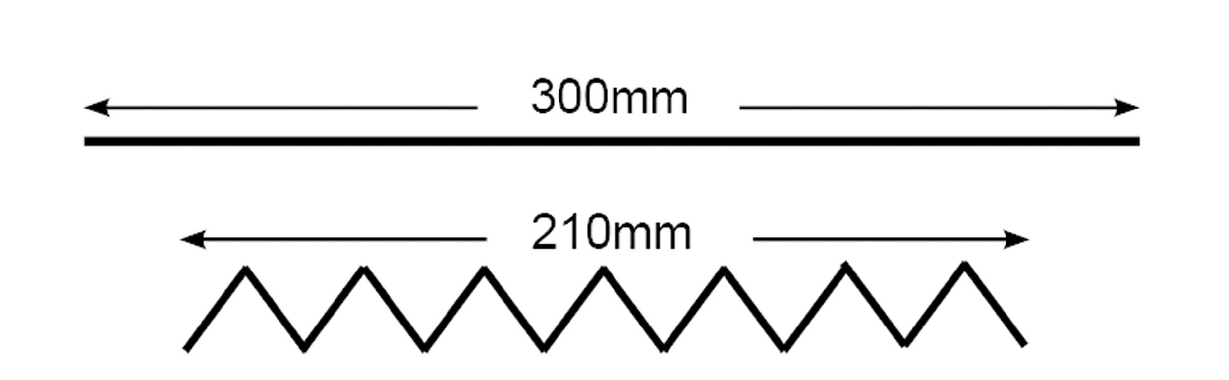
Fig 1b. The same sheet of paper folded
In reality, the substrate has not been shortened in length, but the addition of a profile has enabled the original 300mm length to fit into a lateral length of 210mm. Therefore, adding profile to a surface increases the surface area per meter length.
The profile therefore, provides the coating with a greater surface area, leading to increased coating adhesion.
It is not true to say, however, that if you double the profile you would also double the adhesion.
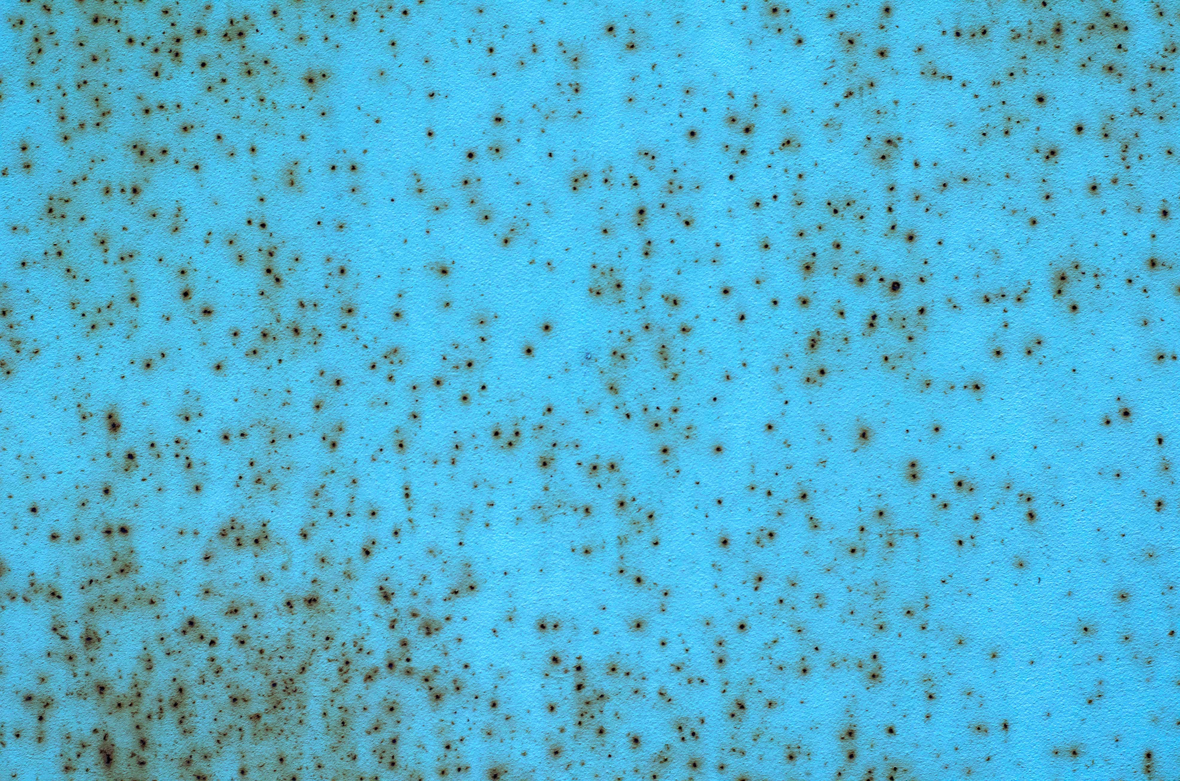
If the profile is too large, the amount of coating required to ensure adequate coverage of the peaks increases, otherwise there is a danger that the peaks remain uncoated or too thinly coated – allowing rust spots or pinpoint rust to occur.
In addition, too much profile can result in solvent entrapment. This is when the coating at the bottom of the profile valleys remains uncured, thus reducing the surface area for adhesion.
Wet film, the top surface of the paint will dry more quickly than that below the surface, as it is easier for the volatile components to evaporate off the surface.
If the skin breaks, uncured paint is washed away, “mud cracking” and the coating fails prematurely, leading to corrosion. Moreover, if the surface profile is too smooth, there may be an insufficient key to produce adequate adhesion – leading to premature coating failures.
There are 4 different methods available for testing surface profile and/or surface roughness:
1. Surface Comparators
2. Replica Tape
3. Surface Profile Gauges
4. Surface Roughness Gauges
Surface Comparators Background
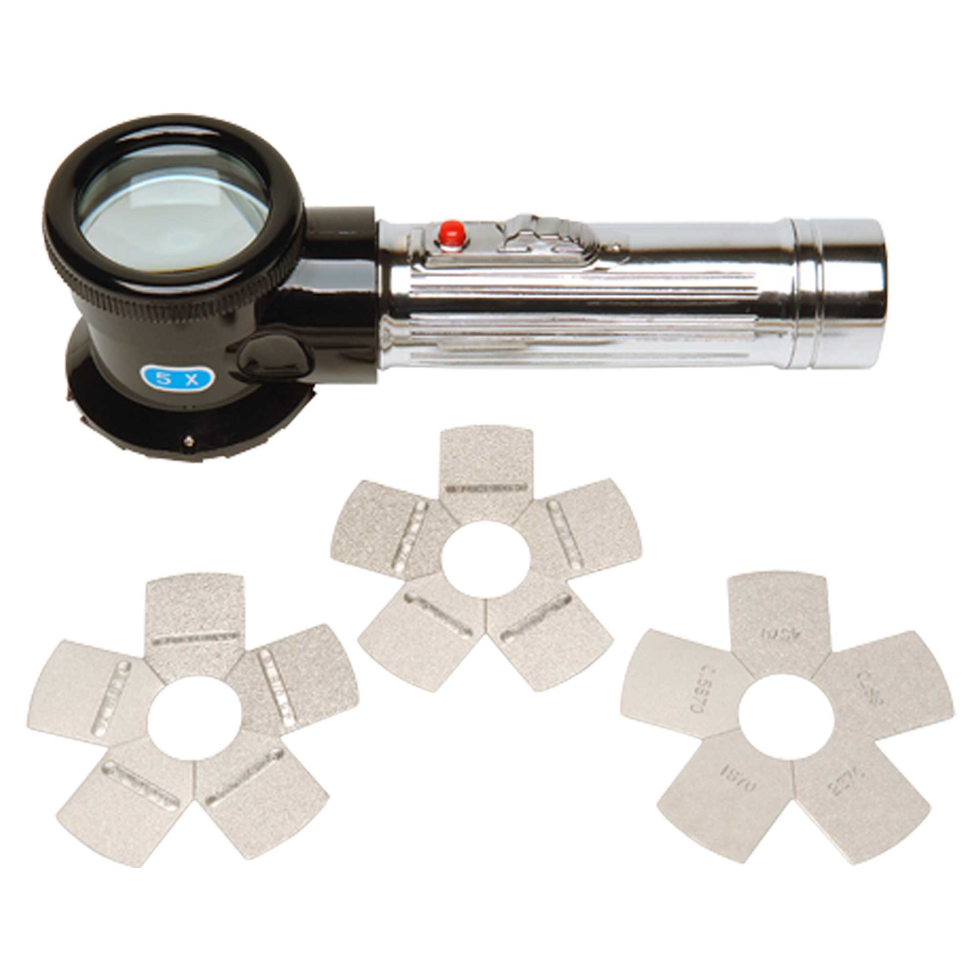
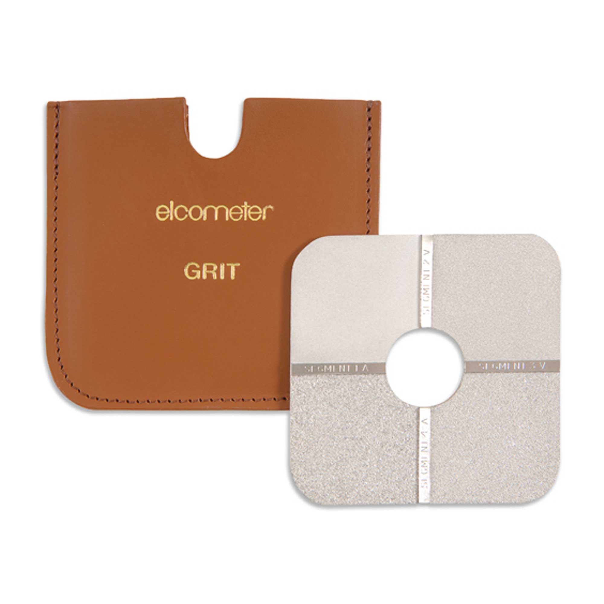
Surface comparators are used to compare freshly-blasted profiles to pre-defined profiles. Standard comparators are available as either grit, shot or sand. The selection of which comparator is used is defined by the media used when blasting.
Surface comparators are used to compare freshly blasted profiles to pre-defined profiles. Standard comparators are available as either grit, shot or sand. The selection of which comparator is used is defined by the media used when blasting.
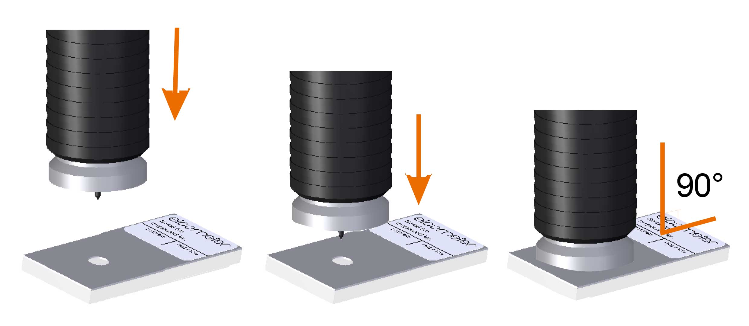
The hole in the middle of some comparators allows the comparator to be placed on the surface, to be assessed so that the comparator and the surface are visible together – enabling clear visual comparisons with the reference profiles. With some products, an illuminated magnifier can also be used to assist with the visual comparison.
In some cases, a tactile comparison using the finger, fingernail or a pin is employed. However, care should be taken not to contaminate the substrate with salts from the skin of the finger. These comparators and the method of use are detailed in ISO 8503-1.
It is important to remember that welds are part of the surface to be assessed. There are comparators (such as the Elcometer Surface Weld Comparator) which are available to measure the quality of weld beads.
Comparators provide the profile values in
- Profile value in microns(μm) – Elcometer 125 ISO Surface Comparators
- Profile value in mils – Elcometer 127 Keane-Tator Surface Comparators
- Profiles in ‘Classes’ or ‘Roughness Averages’ – Elcometer 129 Rubert and Rugotest Surface Comparators
Replica Tape
Whilst surface comparators provide a useful indication of surface profile, the interpretation of the profile is dependent on the experience of the user. Therefore, the use of surface comparators to determine surface profile is a subjective assessment often with variable repeatability and reproducibility results.
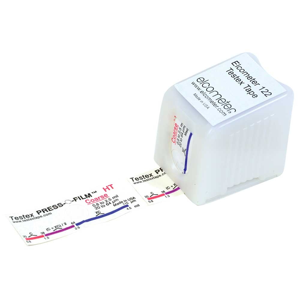
Replica tape, however, produces a numerical value for the peak surface profile and has the often stated advantage of providing a ‘proof of test’ as the used tape can be kept and included in inspection reports (if stored correctly).
Consisting of a foam pad attached to a non-compressible backing strip, the tape is placed onto the surface to be measured with the foam pad in contact with the profile. The foam is then pressed into the profile by rubbing the backing with a plastic stick. The foam replicates the profile of the substrate. The profile in the foam created by the profile in the substrate can then be measured using a micrometer thickness gauge.
The tape is available in four ranges for different profile ranges;
- Coarse Minus (C-) (not used in blast profiles)
- Coarse (C) for 20-64μm (0.8-2.5mils) profiles
- X-Coarse (XC) 38-115μm (1.5-4.5mils), and
- X-Coarse Plus (XC+) for profiles between 115-127μm (4.5- 5.0mils)
For some inspectors, this information will have been overlooked. For those inspectors with stockpiles of old versions of tape, care should be made to ensure that the type of tape is clearly identified on the record worksheet.
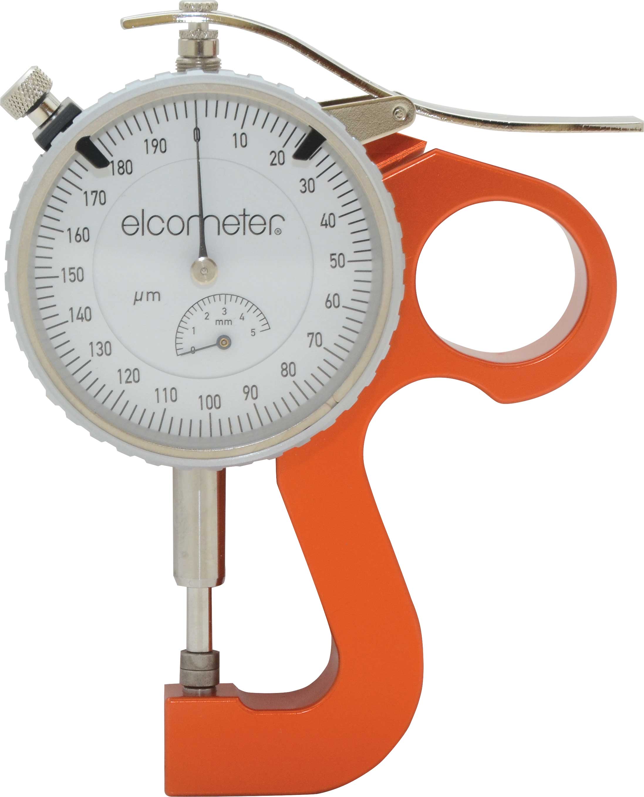
As discussed above, the measurement of the replica tape is taken with a micrometer thickness gauge. Care should also be taken to subtract the original thickness of the non-compressible backing strip window from the total thickness of the backing strip and the foam pad.
Additional consideration should be taken when selecting an appropriate micrometer – not only to ensure the appropriate scale on the dial but also that the appropriate force and anvil area (hence pressure) is applied to the foam.
The Elcometer 124 Thickness Guage has been specifically designed to provide the correct anvil area and measurement force so as not to affect the profile reading. The gauge can also be zeroed to offset the original tape window thickness (typically 50μm (2 mils).
Be aware that replica tape cannot be used twice and that “remeasuring” using the same piece of tape will inevitably lead to crushing of the material, rendering the second test invalid. Also note that if a permanent record of the reading is required, then very careful storage of the tape is necessary.
Identifying and using the correct grade of replica tape to measure the profile requires the inspector to have some idea/knowledge of what the profile is expected to be.
To establish reasonable repeatability from user to user, ASTM 4417 Method C recommends that a minimum of two readings is taken at each location.
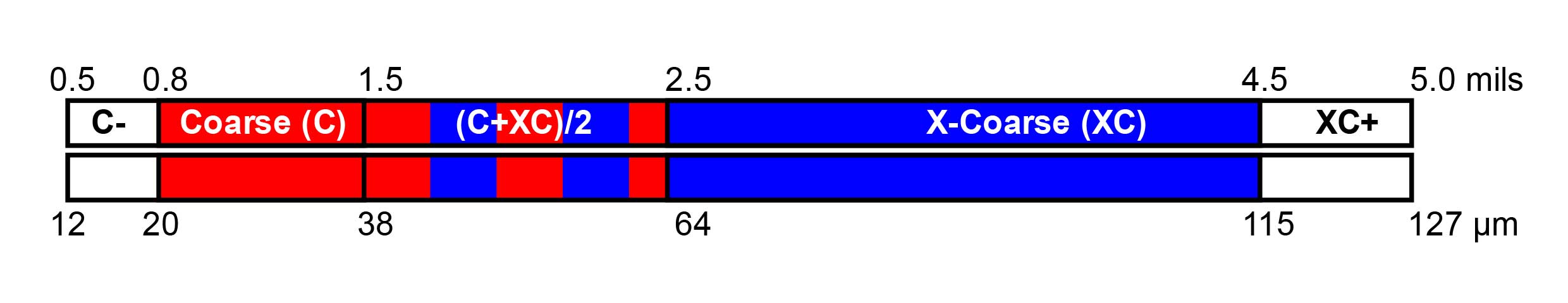
Please note that the range of profile that each grade of replica tape can measure overlaps.
When using the X-Coarse grade of tape and the measured value is in the range of 38 - 64μm (1.5 – 2.5 mils), a measurement must also be taken with the coarse grade of tape. If this reading is also in the range of 38 - 64μm (1.5 – 2.5 mils), then the profile is taken as the average of these two measurements.
When using the coarse grade of tape and the reading of the profile falls in the range of 38 - 64μm (1.5 – 2.5 mils), then a second reading must be taken with the X coarse grade of tape. If the value of the reading with the X coarse grade is greater than 64μm (2.5 mils), then this is the reading to be recorded.
The original reading with the coarse grade is to be discarded. If the value of the reading with the X coarse grade is between 38 - 64μm (1.5 – 2.5 mils), then the profile is taken as the average of the two measurements.
It is important to note that both tape grades must be in the inspector’s toolkit, as simply taking one grade will not be sufficient to record an accurate profile measurement.
As you can see, this apparently simple, fast test could lead to potential errors with untrained inspectors. It is further complicated by the fact that earlier versions of the replica tape did not require this averaging procedure and many users of the tape are unaware of the change.
However, using a profile gauge, we can measure virtually any profile that is used in the protective coatings market (0 - 125μm).
Surface Profile Gauges
A surface profile gauge is an alternative to using replica tapes with varying measurement ranges. These gauges are available with measurement ranges of 0-500μm (0 - 20 mils), 0-1000μm (0 - 40 mils) etc.
A key advantage of the gauge is that it is available with memory for storing batch data. These batches can be downloaded to a PC, smart phone or tablet to produce a permanent record of the measurements.
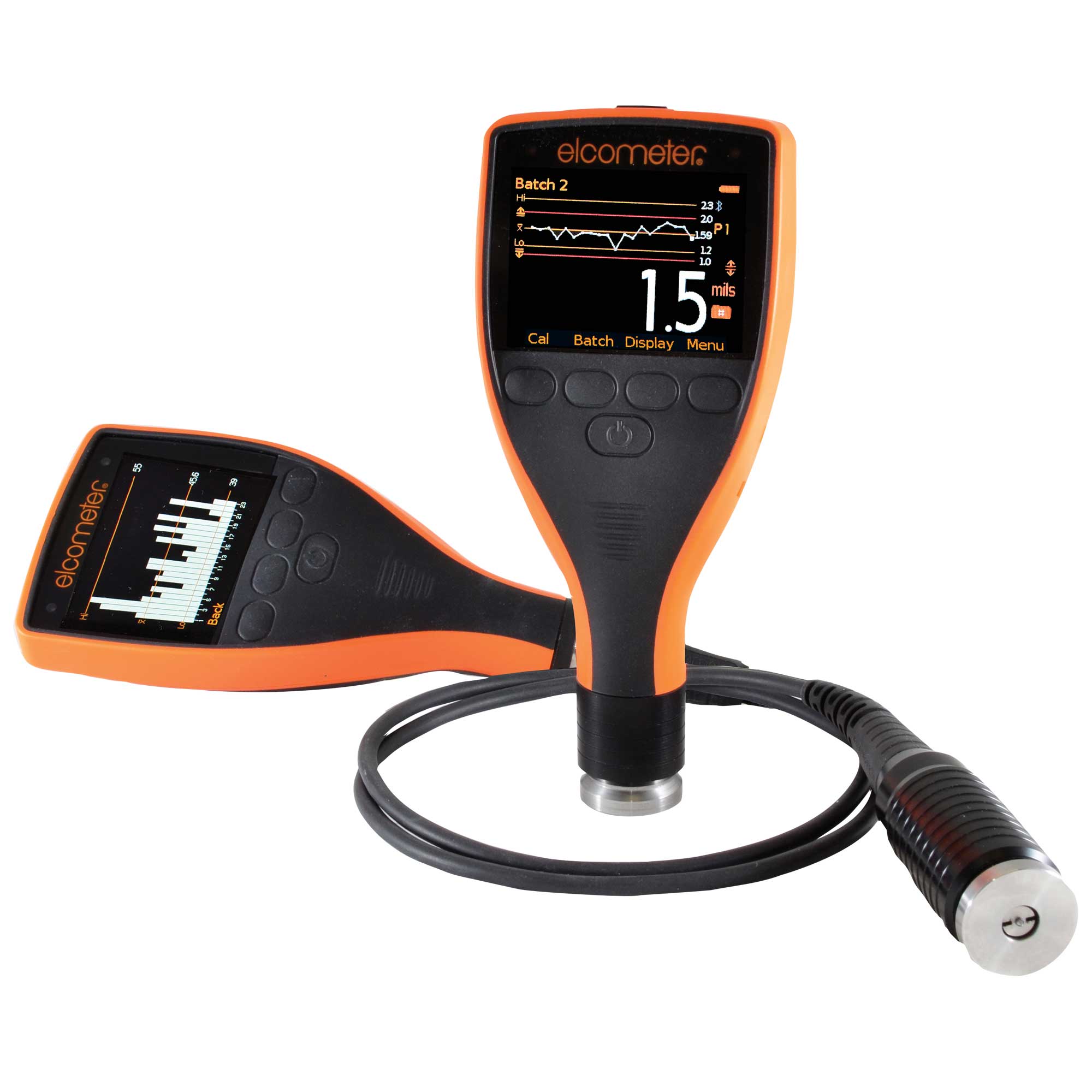
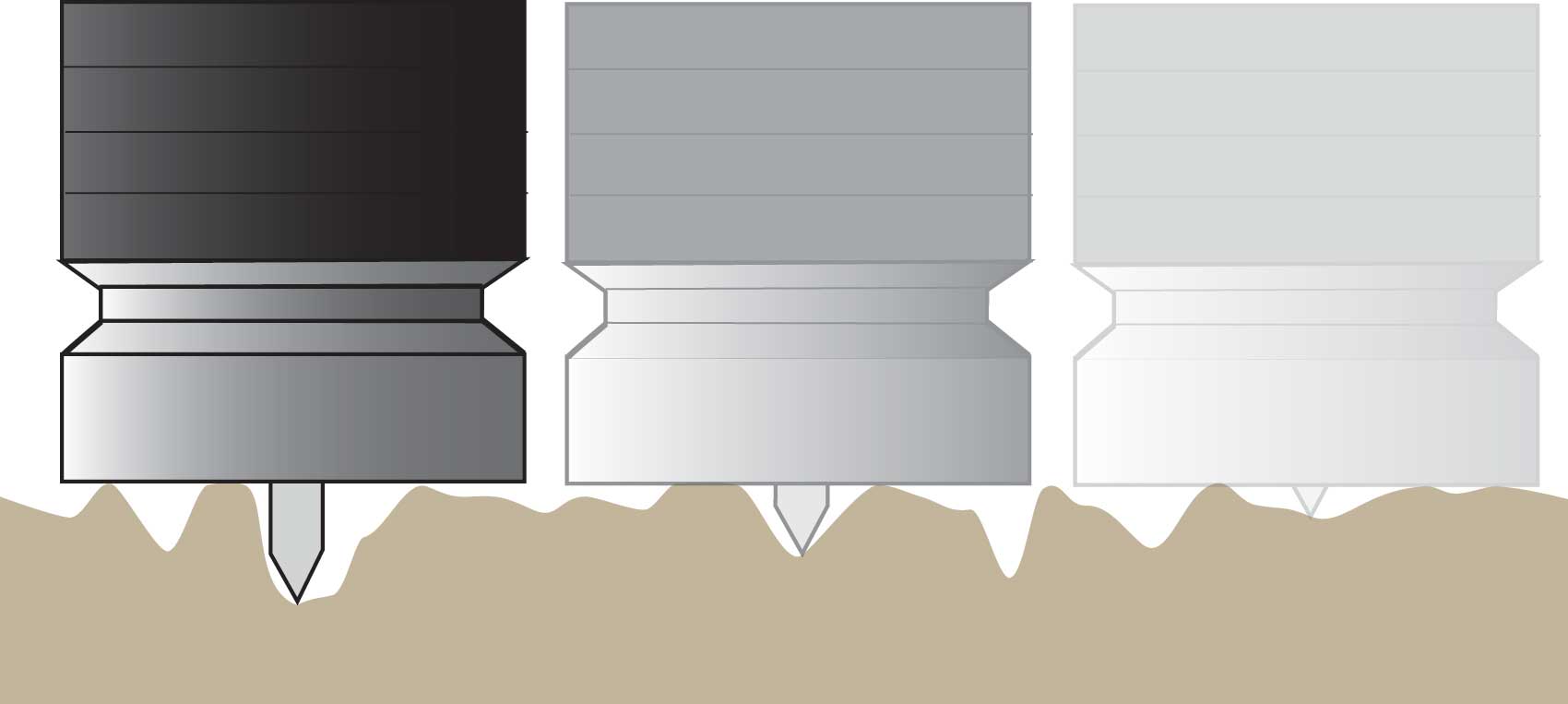
Consisting of a needle with a cone-shaped tip operating within a 25mm diameter flat foot, the Elcometer 224 surface profile gauge measures the peak-to-valley height in terms of the distance between the tip of the needle and the top of the profile (peaks) and the distance between the tip of the needle and the bottom of the profile (valleys).
This method can accurately determine a value for the average peak-to-valley profile.
In accordance with NACE SP0287, the location average should consist of a series of between 5 and 10 instrument readings within a 150 x 150mm (6 x 6”) area. The average of these individual spot measurements provides the user with the peak-to-valley height at that measurement point. The ASTM method states that the gauge should be zeroed using a float glass tile.
When taking readings hold the gauge firmly against the test substrate, do not drag the gauge, as this will accelerate the wearing of the tip. Measure the “profile” at sufficient locations to characterise the surface, either by agreement between parties or by agreed specification.
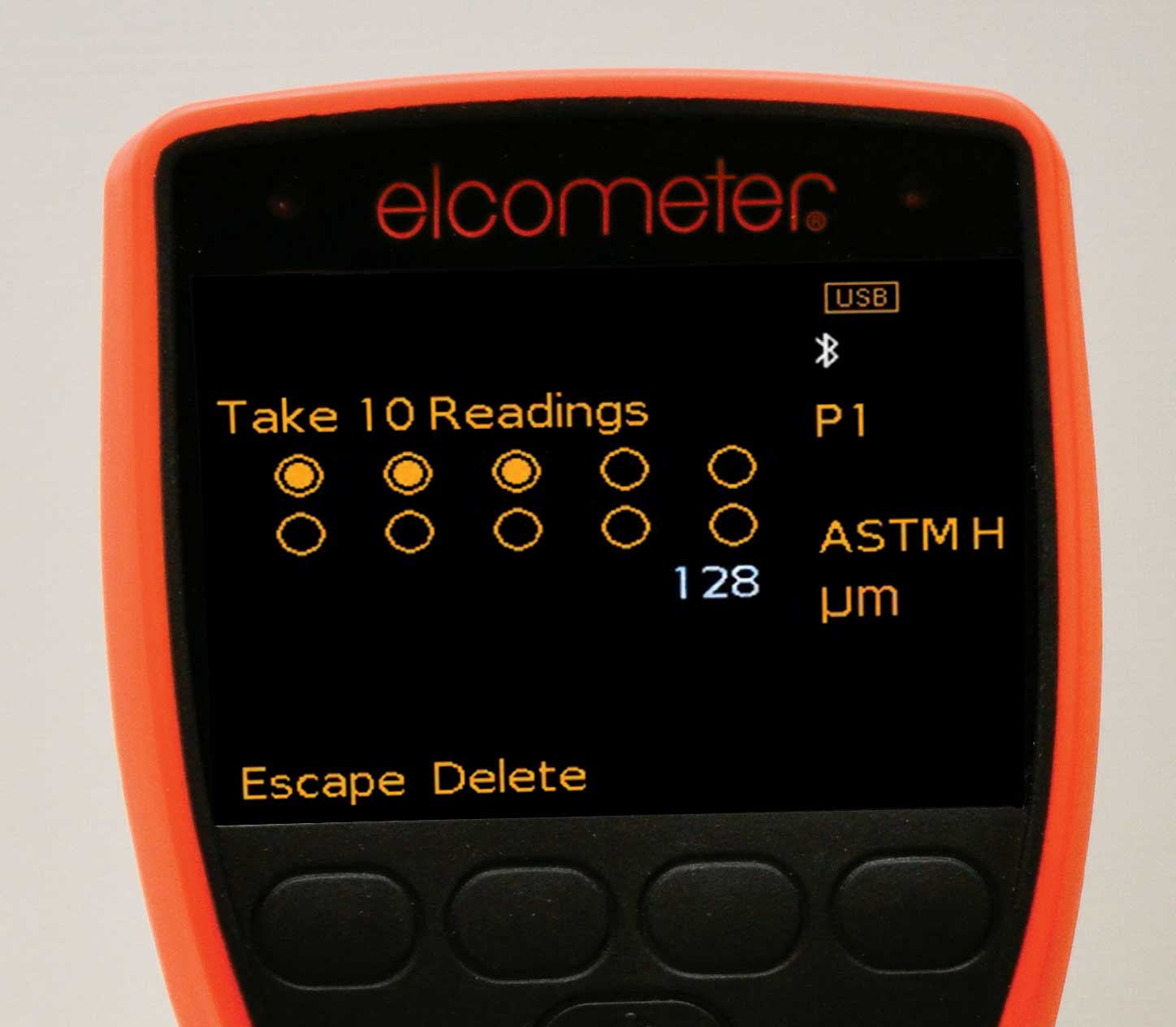
At each location take ten readings and determine the average. Then determine the average across all locations and report that value as the profile of the surface (a recent review of ASTM now allows for either the average or maximum measurement to be recorded).
The use of the Elcometer 224 Digital Surface Profile Gauge provides the inspector with the fastest, most accurate, repeatable and reproducible method of assessing surface profile on flat surfaces.
For each measurement location the user can select the number of readings that will be taken and “averaged” to produce a value. Elcometer recommends a minimum of 2 readings per location.
Using the gauge’s counted average mode, allows the average of the spot readings to be recorded into memory automatically. These readings can then be sent to an Android or iOS enabled device or directly to a PC – via Bluetooth or USB.
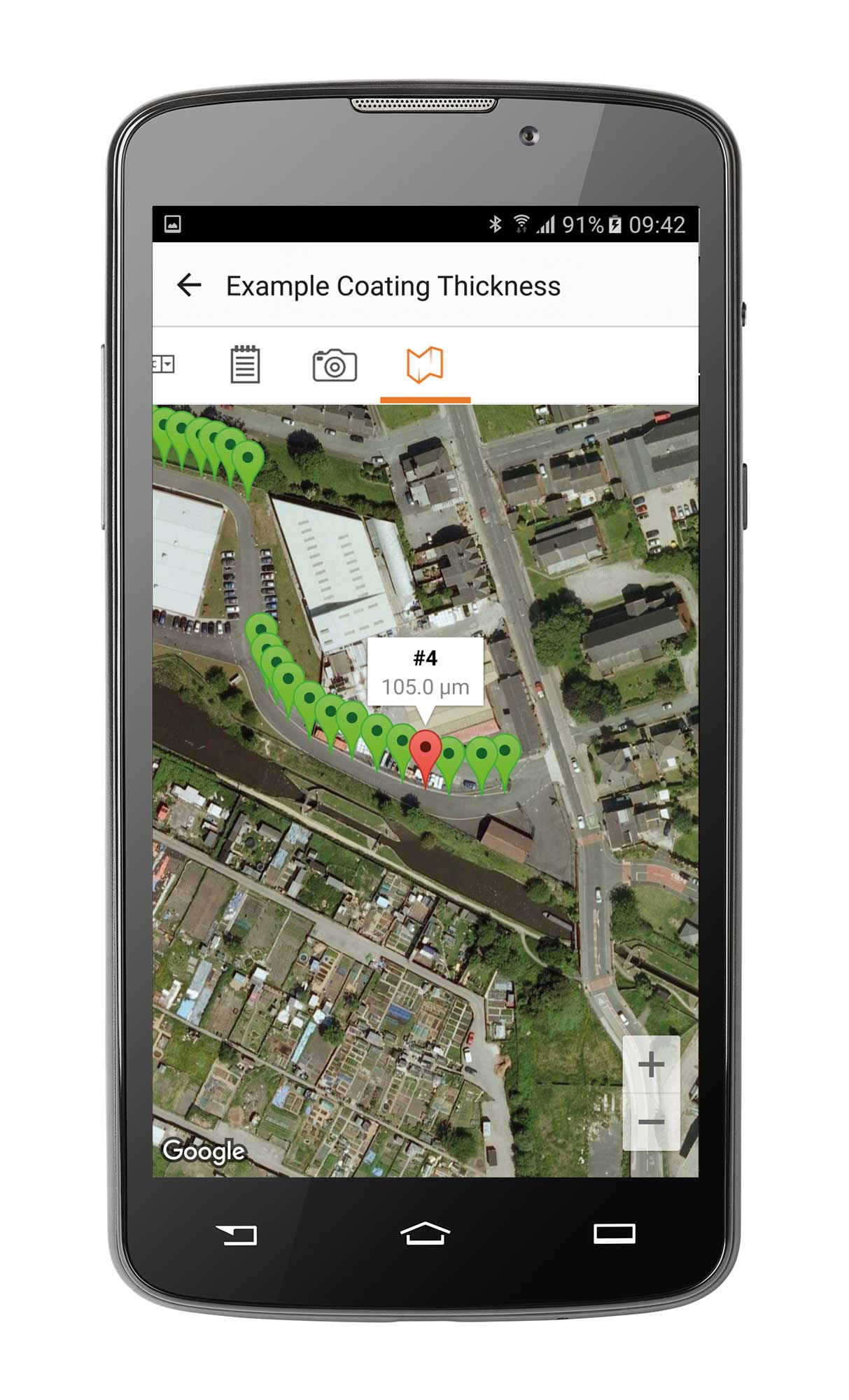
Using the gauge’s live reading mode, in conjunction with an Android and iOS device with GPS, users can not only record the surface profile but also the GPS coordinates. The ElcoMaster® Software will then plot the values onto a map that can be displayed on the screen.
High and low value limits can also be set up on the Elcometer 224 Digital Surface Profile Gauge, allowing users to be warned when the surface profile is either too high or too low to meet the specification.
The tip is a contact component and will wear. This can be seen by the inspector as a flattening off (or rounding) of the pin’s tip.
The tip is replaceable by the user.
The calibration of the Elcometer 224 Surface Profile Gauge can be verified (together with the tip wear) through the use of Elcometer Verification Foils and a glass zero tile.
Elcometer has developed a probe for measuring the profile of cylindrical surfaces such as pipes. This probe can account for the curvature and make the necessary correction to give an accurate repeatable reading of the profile depth.
In certain environments, there can be the risk of electronic equipment causing explosions, such as in the oil and gas industries.
For this application, there are analogue gauges such as the Elcometer 123 Surface Profile Gauge which measures the profile with a needle in a similar way to the Elcometer 224 Surface Profile Gauge.
As these gauges do not have batch memories, users are required to manually record all measurements and calculate the average of these measurements to determine the surface profiles.

Surface Roughness Gauges
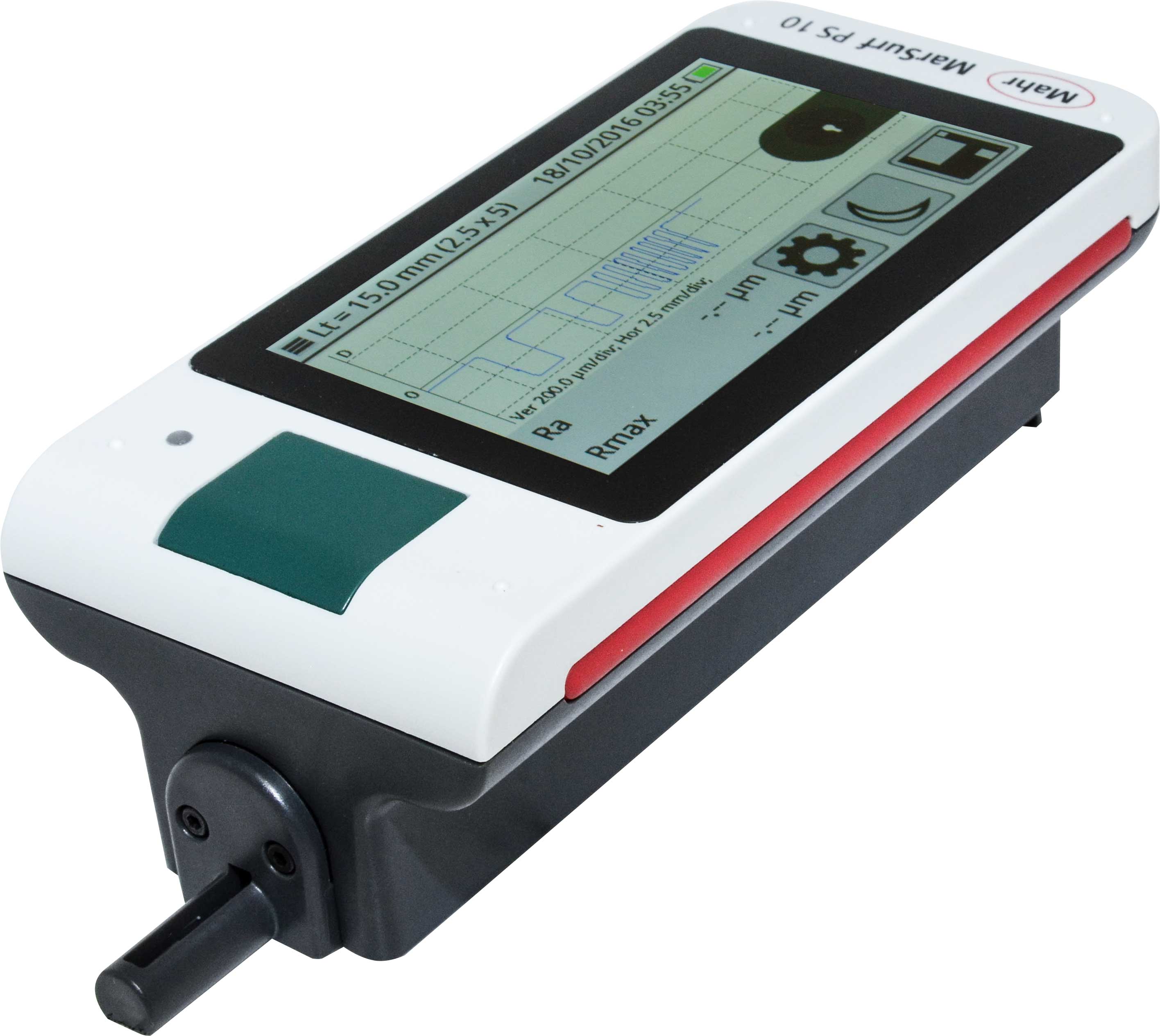
The Surface Roughness Gauge comprises of a stylus (tip) attached to an arm which will drag the tip at a constant rate across a pre-determined linear length. The gauge provides a trace of the surface as well as the depth of the profile.
The gauge will provide a very detailed analysis of the surface profile.
Surface roughness measurement is important to manufacturers of machined components, therefore the gauges are very sensitive to measure almost “smooth” surfaces.
The sensitive (and delicate) nature of this gauge does not make it an ideal unit for use in the field.
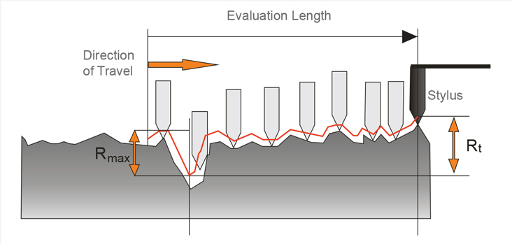
Roughness gauges can also be used to measure blast profiles. Some test standards require the measurement of Rmax, Ra, Rt and Rz which require the measurement of profile over a linear path.
- Rmax: The greatest distance between the highest peak and lowest valley over the sampling length.
- Ra: The average roughness over the sampling length.
- Rt: The distance between the highest peak and the lowest valley within any given sampling length
- Rz: The average distance between the highest peak and lowest valley over several sampling lengths
How Elcometer Can Help
As manufacturers of industry-leading coating inspection equipment, we know how important surface preparation is. That's why we offer a range of surface profile testing solutions to help you during the inspection process.
If you've got any questions when it comes to measuring your surface profile, don't hesitate to get in touch with the team here at Elcometer.